The extent of a source can be small, comparable to or large compared to the point spread function of the experiment. In the first two cases the maximum likelihood technique is recommended to be applied. The command
DETECT/MAXLIK extent edithas to be submitted for the PSPC in pointing mode. To get the proper defaults, for other detectors it is recommended to use (e.g. for HRI) the commands
CREATE/PARFIL EXSP extent ROSAT,HRI
DETECT/MAXLIK extent edit
A parameter file extent.par will be created and offered to be edited (cf. Table 5.16 for PSPC, pointing).
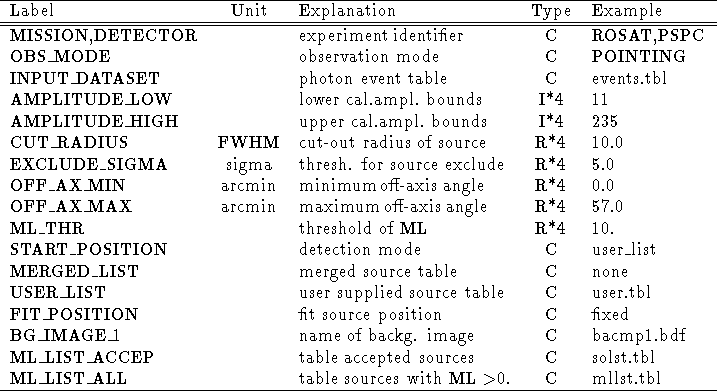
Table 5.16: Parameter file for DETECT/MAXLIK for ROSAT PSPC (fit source extent)
A complete description of all parameters from Table 5.16 can be found in section 5.2.8. Here only some parameters of interest are described:
The Gaussian sigma of the extent and the error in extent (in units of image pixels)is written to the columns :EXT and :EXTERR of the tables ML_LIST_ACCEP or/and ML_LIST_ALL. The likelihood of extent is written to the table column :EXT_ML. Only in case of a large extent likelihood :EXT_ML> 50. the source should be considered as extended. This is because of the limited model used for the point spread function, the Gaussian model.
In case of a bright source a ring integrated profile can be created and tested with ring profiles from more complicated models coming from calibration data. Such a calibration table EXSAS_CAL:psf is existing for the on-axis point spread function. It gives the ring integrated (not yet normalized) surface brightness for energies of 0.1 to 1.7 keV in steps of 0.1 keV and for radii of 1 to 3600 arcsec in steps of 1 arcsec.
Ring integrated profiles from observational (photon event file) data can be created with the command PLOT/RING_PROFILE, see section 5.2.21.
The calibrated on-axis ring profiles can be overplotted to the observed ring profile in the command. In the off-axis case the calibrated ring profiles can be overplotted if they are corrected for the total number of counts in the observed ring profile. In the following example calibrated ring profiles for an off-axis angle of 10 arcmin are overplotted for energies of 0.8 and 1.5 keV onto a ring profile created from a source at an off-axis angle of about 10 arcmin. So a direct comparison is not possible. One should also compute the amplitude weighted calibrated ring profile to test with the data. The amplitude histogram can be created by the BIN/AMPL 10 command and one has to create the ring profile weighted with the amplitudes.
PLOT/RING testdata1:events 851.,-1541.,1000. ? ? ? 100
SET/GRAP stype=1 ltype=0 pmode=1
PLOT/TABLE radevents :RING_RADIUS :INTENSITY
SET/GRAP stype=0 ltype=1
OVERPLOT/ERROR radevents :RING_RADIUS :INTENSITY :ERROR
OVERPLOT/ERROR radevents :RING_RADIUS :INTENSITY :RING_STEP 5
STATISTICS/TABLE radevents :INTENSITY
COPY/TABLE EXSAS_CAL:psf_pspc_10 psf
SET/GRAP ltype=1
COMPUTE/TABLE psf :INTENSITY = :RCTS0D8*{OUTPUTR(3)}*{OUTPUTI(2)}
OVERPLOT/TABLE psf :ANGLE :INTENSITY
SET/GRAP ltype=2
COMPUTE/TABLE psf :INTENSITY = :RCTS1D5*{OUTPUTR(3)}*{OUTPUTI(2)}
OVERPLOT/TABLE psf :ANGLE :INTENSITY
In case of image data the command DRAW/RADIAL_PROFILE
can be used.
One first has to convert the radius from image pixels to arcsec
and the normalized counts to counts per arcmin ![]() before one
can overplot the calibrated profiles.
before one
can overplot the calibrated profiles.