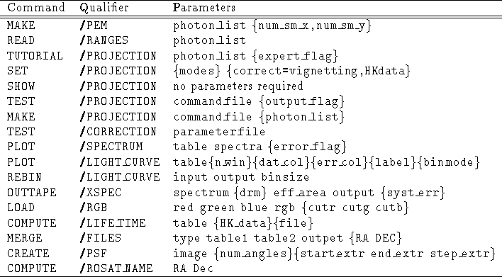
Table 4.8: Utilities -- Curly brackets indicate optional entries
In Table 4.8 the Utilities command syntax is briefly outlined.

Table 4.8:
Utilities -- Curly brackets indicate optional entries
The function of each command will be described in the following:
Various flags can be specified here, at any arbitrary order: when set to INTENSITY the BIN/IMAGE command generates intensity images; when set to ENERGY the BIN/IMAGE command generates energy images (the default is INTENSITY); when set to POINTING the BIN TIME command creates light curves where the time bins which are not entirely exposed to be rejected; contrariwise, when set to SURVEY mode, partially exposed bins in light curves are not rejected, and an EXPOSURE column is created to record the actual exposure times for each time bin (nevertheless in this mode still some time bins are rejected, i.e. those bins where the exposure times are consisting of more than one continuous time interval).
Midas 001> PLOT/SPECTRUM table s y
Midas 001> SET/GRAPH XAXIS=10000,20000
Midas 002> PLOT/LIGHT rates 3 :COUNTS :ERR
To prepare the spectrum, follow all the usual EXSAS steps in order to be able to run the command MODEL/SPECTRUM, included the binning of the detector response matrix (BIN/DETECTOR command). Then you can run
Midas 001> OUTTAPE/XSPEC spectrum matrix eff_area output
where: spectrum is the name of the input table containing the spectrum (output from PREPARE/SPECTRUM).
matrix is the detector response matrix binned according to the binning of the spectrum (output from BIN/DETECTOR).
eff_area is the effective area table (output from CORRECT/SPECTRUM if you used that type of correction or the standard effective area table if you worked with the projection set in CORRECTION mode).
output is the filename for the output files (DO NOT use any extension). This command will produce three ASCII files (check if they all exist):
output.pha_sou is the source+background spectrum
output.pha_bkg is the background spectrum
output.rsp_sou is the detector response matrix
You can then convert the output files (source+bkg spectrum, bkg spectrum and detector response matrix) to XSPEC binary format. In order to ensure that the background and matrix are automatically loaded by XPEC when you load the source spectrum, it is advised to use the following naming convention:
$ mkpha output.pha_sou output
$ mkpha output.pha_bkg output_b
$ mkrsp output.rsp_sou output
This will create the three files output.pha, output_b.pha and output.rsp, containing source + bkg, bkg and response respectively.
In the XSPEC package is NOT possible to rebin spectra. Therefore, the spectra that you move to that system must be rebinned in EXSAS. This means that if you rebinned by a factor of 4 a PSPC spectrum, the XSPEC spectrum will correspond to a ``binned'' PSPC with only 64 bins. Thus, the XSPEC command plot data will produce nonsense: always use plot ecdata to look at the spectrum in counts.
If you follow the naming convention used in the above description (of course, you can replace output with any string), the background spectrum and the detector response matrix will be automatically loaded as you load the source + background spectrum.
Contrary to the XSPEC prescriptions, the detector response matrix
produced by OUTTAPE/XSPEC contains all the information about the effective
area. This means that XSPEC considers the detector to have area 1 cm ![]() ,
and therefore for our case cts/s/cm
,
and therefore for our case cts/s/cm ![]() and cts/s will always be the
same (corresponding to cts/s).
and cts/s will always be the
same (corresponding to cts/s).
Please notice: as to merge PETs it is easy, to merge their descriptor headers (especially the ones containing spatial selections) it is not. Data correction could easily bring wrong results if the user are not perfectly aware of how correction is working! As a general rule, keep always in mind that the descriptor header is valid for those spatial area common to all the merged datasets. To be on the safe side it is suggested, as a first step after merging, to select (via Projection) from the merged PET another PET containing ONLY the photons coming from the spatial portions which are common to ALL the contributing tables. Under this condition, data correction becomes again safe.
The PSF correction is meant to correct for the photon loss due to the limited extraction radius which was defined in the spatial selection of photons from a point-like source. This photon loss depends on the PSF shape and on the defined extraction radius. Moreover, the PSF shape is a function of the photon energy too.
This correction is applicable only in the case of point-like sources and only for circular spatial selections centered on the source itself.
The PSF correction image contains the photon-loss factor for a grid of values of the off axis angle, the extraction radius and the photon energy. The image is created according to a realistic model of the PSF.
In general the command used in default mode generates a good all-purpose image. The number of off axis angles in the grid is defaulted to 60, ranging from 0 to 60 arcminutes, while the number of extracted radius values is defaulted to 10, ranging from 0 to 300 arcseconds. Only in special cases these values need to be modified.