MOXE Instrument Description
Configuration
The MOXE instrument is a set of six
X-ray pinhole cameras that stare continuously at the entire sky, with a
bandpass of 2 to 25 keV (note: the
onboard software has a provision to change the settings of the
lower and upper level discriminators).
The detectors are position-sensitive proportional
counters that are read out by charge division.
Each MOXE module covers 1/6 of the sky (i.e., one face of a cube). For a
square detector with side d, the aperture-detector distance should be f =
d/2 to cover 2pi/3 steradians. For MOXE, f is chosen slightly
smaller so that there is some overlap between the FOVs of the modules
to guarantee full sky coverage in case of a slight
misalignment. We therefore chose a detector area of 32X32 cm**2
and a 'focal
length' f of 15 cm. The pinhole size was chosen such that the diffuse cosmic
background and internal detector background were comparable. For modules
that each view 1/6 of the sky, the pinhole area should be about 1000 times
smaller than the detector area for typical values of diffuse and internal
background.
Single instrument layout
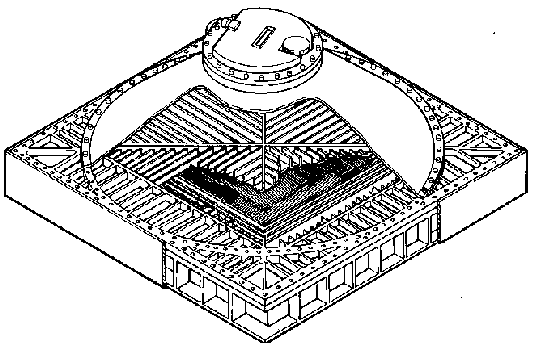
The above picture is a cutaway drawing of one of the MOXE cameras.
All detector body components are made out of aluminum, except the
windows (beryllium), strongback (titanium) and sunshield
(titanium, not shown here). The
cone and detector sides are plated with tin for particle
protection. The six detectors will be placed in holders
that are attached to the satellite at various positions to
ensure satellite components obstruct a minimal part of any
detector's FOV.
In order to optimize the angular resolution, we have chosen an asymmetric
pinhole of 2.556 X 0.625 cm2 (Lochner & Priedhorsky 1991). This
corresponds to 9.7 X 2.4 sq deg on the sky for the on-axis position.
For a given source, the orientation of the long axis of the aperture
as projected on the sky
will vary from one pointing of SXG to the next. Two sources
which are confused in one pointing may not be confused when the projected
aperture is turned to a different angle.
Power consumption and weight
The detector modules include proportional counters,
cones, apertures, high voltage power supplies, preamplifiers, and a
housekeeping/high voltage control box. Each detector
module weighs ~13.5 kg, has an envelope
of about 45X45X26 cm3, and uses ~2.1 Watts (high
voltage on). The
central electronics module includes electronics for amplification, A/D
conversion, event analysis, commanding, telemetry, memory, interface to the
satellite, and two redundant low voltage power supplies. This central
electronics module weighs 35 kg and draws 25.1 Watts of bus power (high
voltage on). Because
Spectrum-X-Gamma flies outside the Earth's magnetosphere, it encounters a
high radiation dose. All electronics are designed to withstand at least
20,000 rads.
Internal works of detectors
The active sensors for MOXE are 32X32 cm2 sized,
1 cm deep, Xenon-filled (with 5% CO2 as a quench gas at a total
pressure of 1.04 atm at 20'C), permanently
sealed, position-sensitive proportional
counters with 5-sided anti coincidence.
Three co-planar grids (two cathodes and one anode) subdivide the volume
in four equally deep layers. The wire grids consist of
parallel 0.254cm spaced stainless steel wires, with a diameter of 75 micron
for the cathode and 13 micron for the anode. Both ends of each cathode
frame are read out separately. Two preamp signals, one from the edge
sections and a second from a 1 cm deep guard layer with its own anode, are
summed to form an anti-coincidence signal. The wire plane that separates
the photon detector layer from the guard layer acts as an over-exposure
sensor, its signal feeding a discriminator circuit that triggers should
the time-averaged anode current be too large.
The detector signals are used to
provide anti coincidence, safety against damage, and input to obtain the
position and energy in the onboard processor.
5-sided anti coincidence and pulse
height discrimination will be used to reject cosmic ray background. The
anti-coincidence plane covers the full area of the detector below the
main detector volume, while the ends of the x- and y-cathode arrays
provide anti-coincidence volumes to guard the sides.
Event energy deposition and localization
Event positions are sensed by charge division in the two resistive cathodes,
one for each axis. The ratio of the two signals at the two ends of a given
cathode is proportional to the position of the photon interaction and
the sum of all four cathode signals is proportional to the photon energy.
Blockages and responses
The low-energy response is limited by the aperture and
detector windows, which are made from respectively 75 and 114 micron thick
Beryllium. A conical assembly holds the 1.6 cm2 pinhole 15 cm
above the detector window. This
assembly is filled with helium gas at ~1 atm
to relieve the pressure differential
across the large detector window. The helium layer absorbs less than 1% of
the photons with energies within MOXE's bandpass. A titanium structure on
top of the detector entrance window ('strongback') supports
any residual pressure differentials, it is designed to withstand
up to about 0.3 atm. The strongback has been constructed in such a way, that
it causes minimum shadowing of the projected image of the aperture
(see Lochner & Priedhorksy 1991).
Intense flux from the Sun, the brightest source in the X-ray sky, raises a
particular problem. Since MOXE covers 4pi steradians, the Sun will always
be in view of at least one detector and sometimes three. The Sun can appear
anywhere in a 20X80 sq deg region, relative to spacecraft
coordinates, as
Spectrum-X-Gamma moves from one pointing to the next. To avoid overloading
the detectors or saturating the telemetry stream, parts of three detectors
corresponding to this 20X80 sq deg region (4% of the
whole sky) are blocked by a heavy titanium
shield. This system is backed up by software that exclude Sun
counts and, for the highest rates, turns off the detector high voltage should
the Sun stray outside the shielded area. The Sun is recognized by its
extremely high count rate compared to other sources.
Digitization and onboard software
Since the total expected counting rate from the six modules is about
260 cts/s
(with about half from point sources), each detected photon can be
individually encoded. We use 24 bits per event: 7 bits for each position
axis, 4 bits of pulse height (photon energy), 3 bits of differential time
information, and 3 bits to identify the detector. The total expected
telemetry rate is 7.4 kbits/s, which is stored in a mass memory of
827 net Megabits, sufficient for 30 hours at average countrate, and
downloaded every 24 hrs at ground contact.
The flight software cannot be modified from the ground but is controlled
by about 1000 variables that can be commanded from the ground.
Hardware status
The six flight detectors are, at the time of this writing, almost all
completely built, and the process of testing has recently been started.
It is expected that all of the flight hardware will be delivered
for integration by December 1994.